VG106
Upgraded Version to VG106 Automation for Plating Plants.
VG106
India's First Automation for Plating Plants.
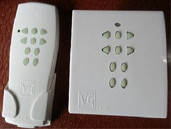
VG RL42 Remote Control Switch
India's First Home Automation with RF based Technology.
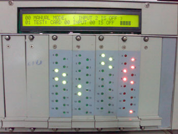
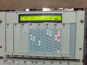
VG 108 PLC
![]()
VG 108 PLC Technical Specification

VG108 Architecture:-
- Card (1) must be Power Supply.
- Card (2) must be CPU card.
- Card (3 or more then 3) can be Digital Input or Output Card.
- Card (A to E or more) are Level Translator Card or Relay.
- FRC Cable connected to Digital Input must connect to Level Translator card only.
- FRC Cable connected to Digital Output must connect to relay card only.
- Once unit is wired, Card's positions should remains fixed.
VG108 basically is consists of :
- 8k Monitor Eprom, 256 RAM used for Monitor program, 24K Application EPROM or PEEPROM (Selectable version), 32K Ram Battery Backup Ram.1K Buffer used for error & plant stoppages logging.
- 16k Buffer for Load logging.
- A Clock to maintain error & Load logging.
- 4K Private Flags. (Retentive).
- 256 Global Flag. (Retentive).
- 3840 Private Counters. (Retentive).
- 240 Global Counters. (Retentive).
- 48 GlobalTimers Programmable having range of 0 to 9999, Selecteble unit of 1sec or 1 Minute (Retentive).
- 8 Alarm Timers having range of 0 To 99 seconds.
- 8 Dwell Timers having range of 0 To 99 seconds.
- 256 Maximum Inputs. Each card is of 16 Inputs.
- 240 Maximum Outputs. Each card is of 16 Inputs.
- Instruments Like Ph, Rh, Temperature, Dosing.
- One RS-232C serial Channel to Communicate with PC.
- One RS485 Channel to communicate with instruments.
- 2 Line 32 Character Self Scan Liquid Crystal Display.
- Necessary wire harnesses.
- Powerful compiled software to program any machine type for zero maintenance time.
VG108 Hardware
All the cards and display described below are plug-in modules in a standard rack unit for ease of maintenance. Once a unit is wired properly one need not have to disturb this wiring to
Pull out any card .Serial communication cable is also brought out on C.P.U Mothercard for ease of CPU card maintenance. Following cards are available in VG - 108 systems. Some of them are essential and some of them are optional
- Power supply card.
- C.P.U Card.
- Digital Input card.
- Digital Output Card.
- Level Translator Card.
- Relay card.
- C.P.U Mother Board.
- Input & Output MotherCard.
- Level Translator & Relay MotherCard.
- Instrument Meters.
- Terminal Card. (Part Number VG108TON00)
- RS485 Card. [Part Number VG108RSC85].
- LCD Display.
- Wire harness (F.R.C).
Power Supply Card (Part Number VG108PSULM)
This is an essential card.- 230V AC +/- 10% Input & following supplies as output.
- +5V D.C Regulated for C.P.U Card.
- +5V D.C Regulated for Digital Input & Output Card.
- +5V D.C for RS-232C Channel.
- +5V D.C for RS-485 Channel. [Optional].
- +5V D.C for Display Backlight. [Optional].
Microprocessor Card (Part Number VG108CPULM)
This is Essential Card.
C.P.U card consist of EPROM, Ram, Timers and Rs232C serial communication and serial communication channel for instruments for suitable RS-485 Protocol. It has built in strong compiler for display routine, zero maintenance machine programming, Interpreter for Plating programming (Optional), communication protocol for meters on RS-485 and protocol for PC on RS- 232C Channel. An Application program can be programmed through PC on Flash Programmable Memory, is supplied optionally and is built in monitor program. A Self Diagnostic Program, Application EPROM Checking program, and a status indicating built in program is strong advantage for zero time maintenance.
Digital Input Card.(Part Number VG108DIP16)
One card is essential.
Each card consists of 16 Inputs. Expandable up to 16 cards.
Different type of digital Input cards are available.+24V Input,+12V Input,6 m.a sink or source type.8 switches mini dip type single pole single way is provided on the card .
It is marked with 1 to 8 & it’s ON Position. To select this card as Zero number, marked 1 switch should be in on position & rest switches in off position(Input 0 To 15). Similarly To select this card as One number card, marked 2 switch should be in on position & rest switches in off position(Input 16 To 31). A rack to rack interface card decides it’s upper half position (Input 128 Input To 255).In front 16 green L.E.D's are provided for input status.
Digital Output Card (Part Number VG108DOP16)
One card is essential.
Each card consists of 16 Outputs. Expandable up to 15 cards.
Different type of digital Output cards are available.+24V Output ,50 moa or 1 A sink type.8 switches mini dip type single pole single way is provided on the card .It is marked with 1 to 8 & its ON Position. To select this card as Zero number card, marked 1 switch should be in on position & rest switches in off position (Output 0 To 15). Similarly To select this card as One number card, marked 2 switches should be in on position & rest switches in off position (Output 16 To 31). A rack to rack interface card decides its upper half position (Output 128 Output To 240).In front 16 red L.E.D’s are provided for output status.
Level Translator Card (Part Number VG108LTC16)
This is optional card.
16 Input cards accept 230V A.C Input (8 M.A) & convert to suitable D.C for Digital Input Card. For ease of removing card 230V A.C connections are brought to euro connector. Also a Mothercard and a F.R.C is necessary to connect Level Translator card to Digital Input card. If this F.R.C is to be connected to Digital Input Card 0 then Inputs of Level Controller Card are considered as Inputs from 0 TO 15.If this F.R.C is connected to Digital Input Card 1 then Inputs of Level Controller Card are considered as Inputs from 16 TO 31 & so on.
A 20 V A.C is required as auxiliary power as these inputs are opto coupled.
Relay Card (Part Number VG108RLC16)
This is optional card.
16 Output card has relay N.O contact as output. Contacts are rated for 230V A.C 2Amp resistive Load. Relays are driven by Digital Output Card .For ease of removing card 230V A.C connections are brought to euro connector. Also a Mothercard and a F.R.C is necessary to connect Relay card to Output card. If this F.R.C is to be connected to Digital Output Card 0 then Outputs of Relay Card are considered as Output from 0 TO 15.
If this F.R.C is to be connected to Digital Output Card 1 then Outputs of Relay Card are considered as Output from 16 TO 31 & so on. Relay contacts are protected with snubber circuit for inductive loads
A 20 V A.C is required as auxiliary power as this outputs are opt coupled.
MotherBoard For CPU & PowerSupply Card (Part Number VG108CMB00)
This is one & essential card.
This card has 2 Euro female connectors for support of power supply & C.P.U card to be plugged in. There are four different type of connectors mounted, One for 230 V A.C (3 Pin screw type), One for display (16 Pin), One for RS232C (9 Pin Dsub male) and One for RS485 (9 Pin female).Also one 16 & one 14 pin Header connection is provided for C.P.U bus to IO Mothercard bus. Interface for display is also mounted on this card.
MotherBoard For Digital Input/Output Card (Part Number VG108IOM00)
One Card is Essential for 2 IO’s card.
This card has 2 Euro female connectors for support of Digital Input/Output card to be plugged in. Also one 14 pin & one 16 pin Header connection is provided for IO Mothercard bus to IO Mothercard /C.P.U Mothercard. Two F.R.C connectors (20 pin Male) are also provided on for connecting to Relay/Level Translator card or to Input/Output to terminal card connector.
MotherBoard For Level Translator, Relay Card (Part Number VG108LRM00)
One is Essential for 2 Level/Relay’s card.
This card has 4 Euro female connectors for support of Level Translator/Relay MotherCard card to be plugged in. Two F.R.C connectors (20 pin Male) are also provided on for connecting to
Digital Input/Output card.20 pin screw type connector (4 connectors of 5 Pin) is also provided for external connection. 2 pin screw type connector is also provided for 20V A.C input for auxiliary power supply connection.
Instrument Meters.
- Temperature Controller Meter. [Optional].
- Rectifier Controller Meter. [Optional].
- PH Controller Meter. [Optional].
- RH Controller Meter. [Optional].
Terminal Card
This is optional card, is meant for Digital Input/Output external connection. An Auxiliary 24V D.C should be supplied for working of opto isolated Input/Output. Two F.R.C connectors (20 pin Male) are also provided on for connecting to Digital Input/Output card.20 pin Screw type connector (4 connectors of 5 Pin) is also provided for external connection.
RS485 Card (Part Number VG108RSC85)
This card is connected to 9 pin female connector of CPU Mothercard. And its 3 pin outlet connectors are connected to all instruments.
Display Card
2 line 32 character self scan display with its cable.Display is connected to CPU motherboard's 16 pin connector.
- [Part Number VG108DSP00] Non Backlight
- [Part Number VG108DSPBL] Having Backlight
Wire harness (F.R.C).
- Wire harness (F.R.C) to connect Input to Level Translator OR Output to Relay.
- [Part Number VG108FRC20]
- Wire harness (F.R.C) to connect bus system.
- [Part Number VG108HEA14] for 14 pin This is essential for Digital Input/Output motherboard to another digital Input/Output motherboard OR to terminal card connector.
- [Part Number VG108HEA16] for 16 pin This is also essential for CPU motherboard to Digital Input/Output motherboard connection.
This is essential for Digital Input/Output to LevelTranslator/Relay card OR to terminal card connection.