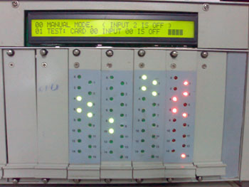
VG106
Upgraded Version to VG106 Automation for Plating Plants.
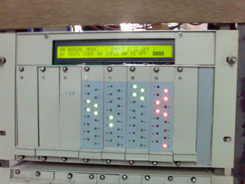
VG106
India's First Automation for Plating Plants.
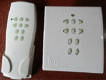
VG RL42 Remote Control Switch
India's First Home Automation with RF based Technology.
Temperature Controllers
Temperature Controller Without DataLogger Model: TC-R200
Temperature Controller With Data Logger Model : VG-TC
Temperature Controller Without Datalogger Model: TC-R200 :-
![]()
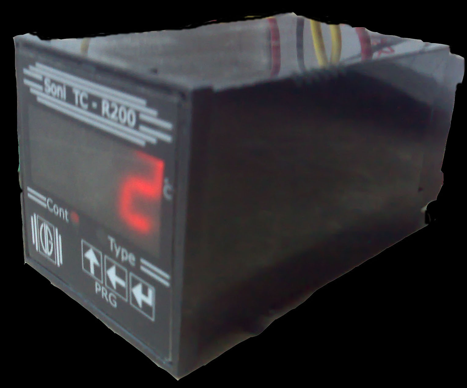
Temperature Controller TC-R200 Features:-
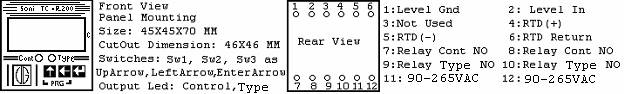
It is 3 digit-7 Segment with calibration Temperature-Controller Instrument, used to measure and control temperature for 0 to 200 centigrade from a sensor RTD, has a built-in level controller (Can be used as door switch), and a control-Relay, which can be cut-off if level input is not sensed.
It also has an additional relay, Type-Relay, which can be used with different functions as below:
- To create Flashing-Error if temperature is not reaching to required
- Set-point.
- To create On-Type(Not Flashing) Error if temperature is not reaching to required Set-point.
- It can be used as In-Range to set relay on when temperature is In-Range (Settable Range-Low to Range-High).
- Two Point Controller as Low-Point.
- Two Point Controller as High-Point.
- A relay indication is provided in front for relay status and three membrane-push-buttons, Up-Arrow, Left-Arrow, Enter-Arrow are provided to view and edit parameters.
There are two modes for operation.
Click here to Download Operating Help
Note: If two wire RTD is used then short pin 5 & 6 and re-calibrate to compensate wire length of RTD (If large length).
- Measure-Mode
- Program-Mode
At power on and if none of switch is pressed display start showing Measured Temperature value in centigrade if calibrated correctly and relays start functioning as per parameter settings. Press Sw3 (Enter-Arrow) to see Set-Point, Or press both Sw1 (Up-Arrow) and Sw2 (Left-Arrow) to Program Parameters.
There are 14 parameters can be viewed/edited one by one in this mode.
When user is in Measure-Mode and presses Sw1 and Sw2 both together, user enters in this mode with display shows first parameter 5P.
Parameters are abbreviated on display and are shown as follows:
- Set-Point abbreviated as 5P.
- Proportionate/Control as Po.
- Band as bA.
- Proportionate-Time as Pt.
- Alarm-Time as At.
- Delay-Time as dt.
- Type as ty.
- Range-Low as rL.
- Range-High as rH.
- Low-Level Sense/No-Level Sense as LL.
- Heating/Cooling as HE.
- Lock-Edit/No-Lock as LE.
- Calibrate-Low as CL.
- Calibrate-High as CH.
To exit any time from Program mode press both Sw1 (UpArrow) and Sw2 (LeftArrow) again.
Note: If this mode is left for sometime without any action for preset internal time, Measure-Mode will be established automatically.
For Further Help please download Help File for TC-R200
Temperature Controller With Data Logger Model : VG-TC
![]()

Temperature Controller VG-TC Features :-
- 240V 10% AC Input Auxillary Supply
- 12V 10% AC Supply for Level Sensors
- 0 to +2.5V for Sensor
- 4 Level Sensors
- RS-485 port for Logging & Display
- 5 Pushbuttons for Settings
- Outputs:-
- Relay for Low set point
- Relay for Control set point
- Relay for High set point
- Relay for Error
- 2 Relay for Dozing (Optional)
Instrument Front View:-
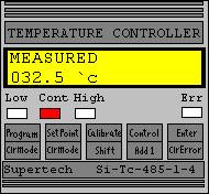
- Low: - Low Relay Output on Indication
- Cont: - Control Relay Output On Indication.
- High: - High Relay Output on Indication.
- Following push button is given for settings.
- Program/ClrMode
- SetPoint/ClrMode
- Calibrate/Shift
- Control/Add1
- Enter/ClrError
Instrument Back View:-
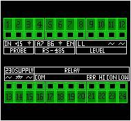
- Input +ve of Pt100 Amplifier
- Output +15V for Pt100 Amplifier
- Output Ground(+15V) for Pt100 Amplifier
- A7 Connection of RS485, connected to A7 of RS485-To- RS232-Converter card. This is also connected to all A7 connection of all other Instruments.
- B6 Connection of RS485, connected to B6 of RS485-To- RS232-Converter card. This is also connected to all B6 connection of all other Instruments.
- Common Connection of RS485, connected to Common of RS485-To- RS232-Converter card. This is also connected to all Common connection of all other Instruments.
- En (Enable) Connection of RS485, connected to En of RS485-To- RS232-Converter card. This is also connected to all En connection of all other Instruments.
- LL (Low Level) connected to Low Level Probe.
- Optional For OverFlow.
- 1Not Used
- 12V AC Supply for Level Controller (Built-In).Also used as common point for Low Level & OverFlow sensor.
- 12V AC Supply for Level Controller (Built-In).
- 230 V AC Supply.
- Supply Earth.
- 230 V AC Supply.
- Common point For All Relays.
- Not Used.(Optional For Dozing)
- Not Used.
- Not Used.
- Not Used.
- Normally open contact of Error relay.
- Normally open contact of High temperature relay.
- Normally open contact of Control temperature relay.
- Normally open contact of Low temperature relay.
Other Settings (Provided through push button):-
- Give Password
- New Password
- Locking System
- Meter ID (Number)
- Decimal Place
- Set Point: Low
- Set Point: Control
- Set Point: High
- Dead Band Width
- Proportion Band
- Proportion Time
- OnOff Control
- Heating Control
- Control Alarm Time
- CalibrationLoPoint
- CalibrationHiPoint
Error:-
- Error1 Check Relay Probe
- Error2 Tank Low Level
Note: For Further Help please download Help File for VG-TC